
Introduction
A Simple Vapour Compression Refrigeration (VCR) System is a common and efficient method used for cooling in
various applications,
such as in refrigeration. The basic working principle involves the circulation of a refrigerant through a
closed loop, undergoing
phase changes to absorb heat from one area and release it in another. The refrigerant is sealed condition in
an airtight mechanism
and is compressed in a compressor which permits the transfer of heat energy.
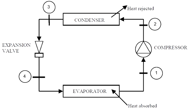
Components of Vapour Compression Refrigeration cycle
The following are the main components of the VCR cycle:
1. Compressor : The vapour at low pressure and low temperature enters the compressor from the evaporator
where
it is compressed to high pressure and high temperature.
This high pressure and temperature vapour refrigerant are discharged into the condenser through the discharge
valve.
2. Condenser :
The function of the condenser is to provide a heat transfer surface through which heat passes from the
refrigerant to the
condensing medium which is either water or air.
3. Expansion Valve : As the high pressure subcooled liquid refrigerant from the condenser passes
through the expansion valve its
pressure and temperature is reduced and refrigerant comes out mostly in liquid state.
4. Evaporator : In the evaporator of any cooling system contain pipes or coils where the liquid
refrigerant has low temperature
and low pressure. In evaporator liquid refrigerant is evaporated and transfer into vapour refrigerant where
the temperature and pressure is both are stays in low.
In the beginning of the process the liquid refrigerant change its state of phase liquid to vapour and after
that the liquid refrigerant
change state of phase from vapour state to liquid. Its function is to provide a heat transfer surface through
which heat can pass from the refrigerated space into the vapourizing refrigerant.
Working of Vapour Compression Refrigeration cycle
The following are the process of VCR cycle required to complete one cycle:
(a) Compression
(b) Condensation
(c) Expansion
(d) Vapourization
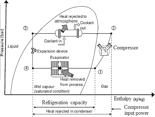
a) Compression :
The low-pressure vapour in the dry state is drawn from the evaporator during the suction stroke of the
compressor. During compression Stroke,
the pressure and temperature increase until vapour temperature is greater than the temperature of condenser
cooling medium (air or water)
At point 1 in the diagram, the circulating refrigerant enters the compressor as a saturated vapour. From point
1 to point 2, the vapour is
isentropically compressed (i.e., compressed at constant entropy) and exits the compressor as a superheated
vapour.
b) Condensation :
When the high-pressure refrigerant vapour enters the condenser heat flows from the condenser to the cooling
medium thus allowing the vapourized
refrigerant to return to the liquid state.
From point 2 to point 3, the vapour travels through part of the condenser which removes the superheat by
cooling the vapour. Between point 3 and point 4,
the vapour travels through the remainder of the condenser and is condensed into a saturated liquid. The
condensation process occurs at essentially constant pressure.
c) Expansion :
After condenser the liquid refrigerant is stored in the liquid receiver until needed. From the receiver it
passes through an expansion
valve where the pressure is reduced sufficiently to allow the vapourization of liquid at a low temperature of
about -10°C.
Between points 3 and 4, the saturated liquid refrigerant passes through the expansion valve and undergoes an
abrupt decrease of pressure.
That process results in the adiabatic flash evaporation and auto-refrigeration of a portion of the liquid
(typically, less than half of the liquid flashes).
d) Vapourization :
The low-pressure refrigerant vapour after expansion in the expansion valve enters the evaporator or
refrigerated space where a considerable
amount of heat is absorbed by it and refrigeration is furnished.
Between points 4 and 1, the cold and partially vapourized refrigerant travels through the coil or tubes in the
evaporator where it is vaporized
by the warm air (from the space being refrigerated) that a fan circulates across the coil or tubes in the
evaporator.
C.O.P. of Vapour Compression Refrigeration System:
[h3 = h4, Since during expansion 3-4, the heat remains unchanged].
Types of VCR Cycle:
1. Cycle with dry saturated vapour after compression.
2. Cycle with wet vapour after compression.
3. Cycle with superheated vapour after compression.
4. Cycle with superheated vapour before compression.
5. Cycle with under cooling or sub cooling of refrigerant.
Advantages of VCR Cycle:
1. It has a smaller size for the given capacity of refrigeration.
2. It has less running cost.
3. It can be employed over a large range of temperatures.
4. The coefficient of performance is quite high.
Disadvantages of VCR Cycle:
1. The initial cost is high.
2. The prevention of leakage of the refrigerant is the major problem in the vapour compression system.
3. More wear and tear and noise due to moving Parts.